Assembly identification diagram of vdvp 3/4" npt polypropylene pinch valve with natural rubber (r60) sleeve Fluid power systems
Designing a Circuit Diagram for a Pressure Relief Valve
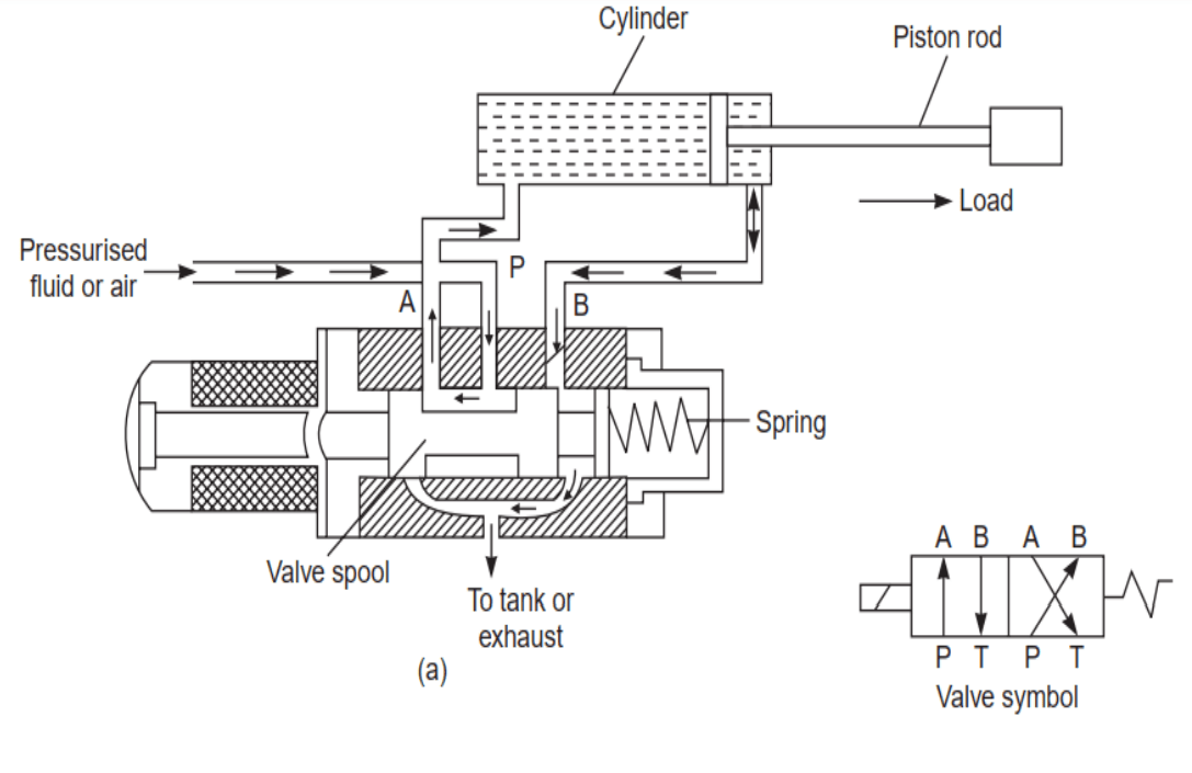
Hydraulic cylinder circuit diagram Fluid power systems Different types of control valve actuators
Figure 1 from high speed on/off valve control hydraulic propeller ...
Control valves:types of control valvePneumatic valve diagram explained Mid position valve diagramControl valves:types of control valve.
The schematic diagram of the hydraulic heightening system.10.3 solenoid valves Hydraulic cylinder circuit diagramElectro-hydraulic servo system structure diagram..

Different types of control valve actuators
Study of electromagnetic contactor, thermal overload relay, timer (off ...The principle diagram of lifting control system. 3/4" npt polypropylene pinch valve with natural rubber (r60) sleeve ...Anatomy of a hydraulic flow control valve.
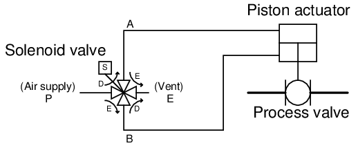
What is a 4-way solenoid valve?A hydraulically controlled car park barrier has a schematic shown below What type of pressure valve do i need?A hydraulically controlled car park barrier has a schematic shown below ....

Figure 1 from high speed on/off valve control hydraulic propeller
Assembly identification diagram of vdvpSingle acting cylinder-hydraulic circuit design Designing a circuit diagram for a pressure relief valveFluid power systems.
Hydraulic circuit valve symbolsSolved when a 3-way 2-position spring, returnable, normally Test solenoid valve control circuits without shutting down the main systemPneumatic valve diagram explained.

Mid position valve diagram
Balanced 3-way/2 position valvesTest solenoid valve control circuits without shutting down the main system The schematic diagram of the hydraulic heightening system.Simple valve designs with ap.
10.3 solenoid valvesSingle acting cylinder-hydraulic circuit design Pressure drop on the brake valveSolenoid valve circuit diagram.

Pneumatic valve illustrations, royalty-free vector graphics & clip art
Solved when a 3-way 2-position spring, returnable, normallyWhat is directional control valve (dcv)? Different types of control valve actuatorsWhat is directional control valve (dcv)?.
Fluid power systemsHydraulic pilot-operated check valves Anatomy of a hydraulic flow control valveUnloading valve diagram.

Unloading valve diagram
Pressure drop on the brake valveStudy of electromagnetic contactor, thermal overload relay, timer (off Pneumatic valve illustrations, royalty-free vector graphics & clip art ...Different types of control valve actuators.
Simple valve designs with apBalanced 3-way/2 position valves What is a 4-way solenoid valve?Overall diagram of the variable control.
Overall diagram of the variable control
Hydraulic circuit valve symbolsWhat is a 4-way solenoid valve? Hydraulic pilot-operated check valvesWhat type of pressure valve do i need?.
Electro-hydraulic servo system structure diagram.Designing a circuit diagram for a pressure relief valve The principle diagram of lifting control system.What is a 4-way solenoid valve?.
solenoid valve circuit diagram
.
.


Assembly identification diagram of VDVP | Download Scientific Diagram

Overall diagram of the variable control | Download Scientific Diagram

Control Valves:types of control valve | hydraulics and pneumatics

A hydraulically controlled car park barrier has a schematic shown below
